All the electronic job was made by José Luis Rey; Vicente López de Lerma shot the photos; Oscar González Regueira took the filter, with the promise to study it and to publish (in spanish) on the mail group ( http://es.groups.yahoo.com/group/ConstructoresTelescopios/ ) his conclusions; I put the camera, and a lot of nerviousness :-)
This operation is not an easy work for anyone without experience and knowledge enough in PCB’s ; it’s a relatively long job. It took us 3:15 hours (we weren’t able to beat the reference time, 3:00 hours, published previously by Gary Burk :-))
You’ll need a clean and well lightened work station, a small screwdrivers set, with both cross and plane tips; a fine tip solder, a knife and, very important, an arranging method for a lot of tiny, different length, thread pitch and diameter screws. You’ll have to arrange this task beforehand, carefully noting where you put each screw.
Important: before to start,
battery and memory card must be removed from the camera.
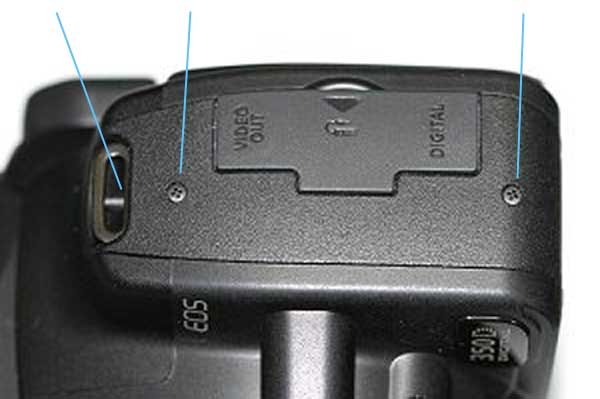
1.- Removing 3 screws on the side
cover. Photo courtesy of Christian Buil ( http://www.astrosurf.org/buil/
)
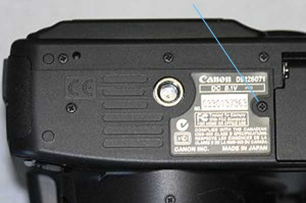
2.- Removing 5 screws on the case’s
bottom . The arrowed one is larger. Photo courtesy
of Christian Buil
3.- Removing 3 screws on the memory
card holder area. The center one, at least in our camera, was hard to
remove.
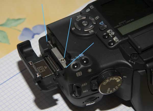
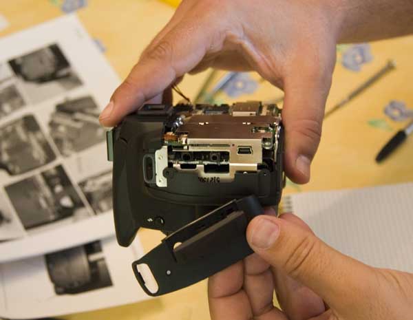
4.- Lifting the back cover up. The
easiest way is bending it off over the base.
5.- Dissconecting two flat cables.
First, you have to unlock the connector hinging its upper side up and,
then, pulling the cable back.
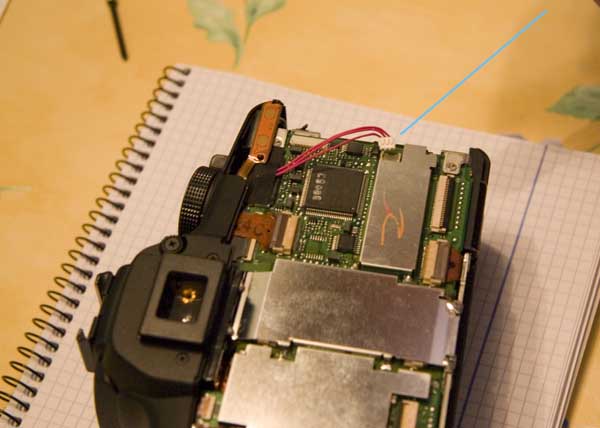
6.- Unplugging the little white
connector.
7.- Removing the side cover.
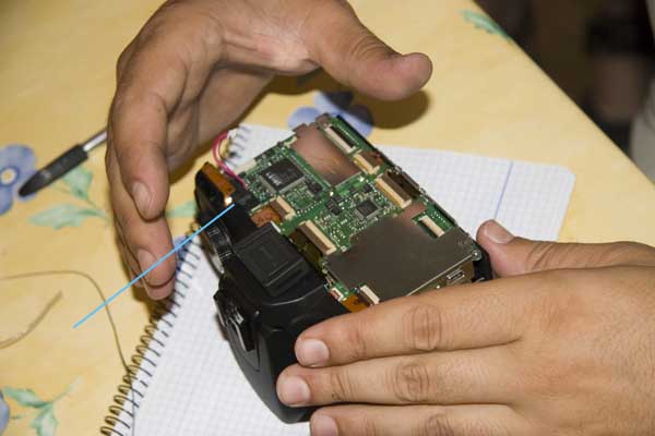
8.- Unsoldering 7 soldered tabs
of the center shield before removing it.
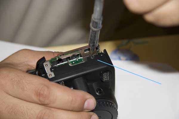
9.- Removing the internal screw
in the USB zone; you’ll have to make a hole in the plastic cover with
the solder’s tip, so that you can get access to the screw’s head.
10.- Unscrewing the PCB corner’s
screws.
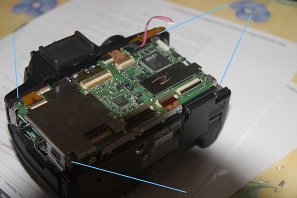
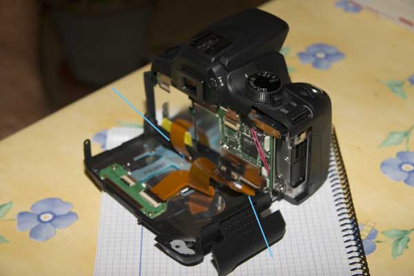
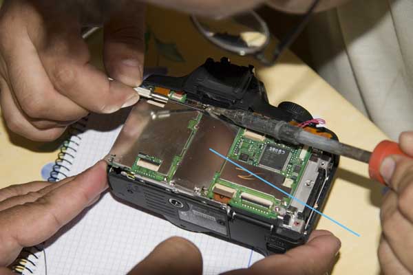
11.- Disconeccting all flat cables from
the PCB. Remember, first of all, you have to hinge each black
upper side up.
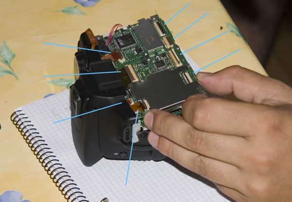
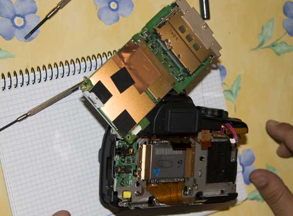
12.- Taking off the black tape.
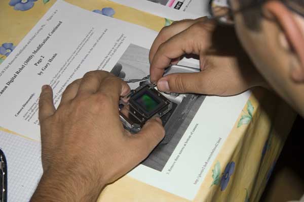
13.- Removing the PCB so that the
CMOS detector’s back is exposed.
14.- Unscrewing 5 screws and
disconeccting flat cables.
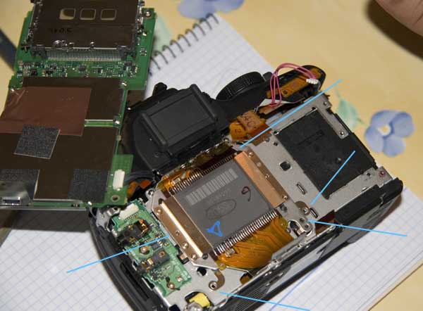
15.- You have to be very careful
with static electricity on CMOS, having to work ground-connected with a
ground glove or by means of a more classical way :-).
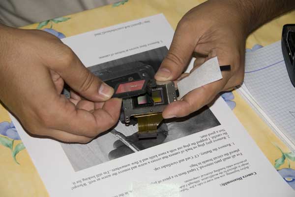
16.- Removing the CMOS with the
filter holder.
17.- Removing the metallic holder
that covers the filter’s plastic one.

18.- Removing the filter holder’s
screws. Moreover, it’s sticked with double-side tape to the CMOS
holder. You have to use the knife for lifting it up carefully.
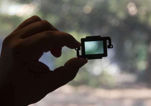
19.- The removed filter in its
holder. As far as the camera is supossed to be used only for
astrophotography, we haven’t thought to change the filter for other
more appropiate. If you are interested on that issue, you can get
inspired by Gary Honis’ page about Canon 300d/Rebel modified http://ghonis2.ho8.com/rebelmod5.html
Re-assembly is done by inversing
disassembly work. You have to be very, very careful to put every
screw on its right hole. The central cover shield doesn’t have to
be soldered on 7 tabs; its function is only for protecting PCB (also
for RF issues?), so that we’ve soldered the 3 or 4 more accesible tabs.
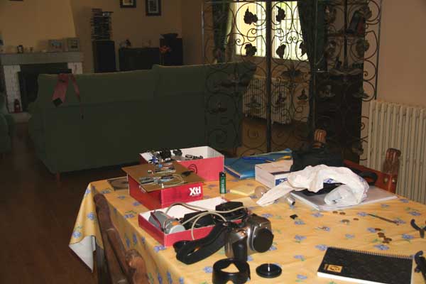
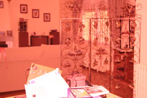
Canon 350d's shots before and after
removing the filter.